An overview of sonar techniques for maritime navigation
Anti-collision sonar for navigators
Many types of sonar are available on the marine acoustic equipment market, which aid in assessing underwater conditions. They vary in capabilities and price. When selecting a device for a navigator, it's crucial to be aware of the differences in sonar technology. This paper aims to clarify these differences and assist captains, shipowners, and navigators in making decisions about equipping a ship or yacht with a navigation sonar before purchasing one.
Introduction
Forward-looking sonars (FLS) are designed to detect obstacles ahead of a vessel, such as shoals, protruding obstacles, or floating obstacles, as well as to provide alarms during automatic navigation. This is a relatively new type of sonars (at least in non-military applications). Currently, there are a limited number of FLS sonars available on the market.
Here is a short list of types:
Modele FarSounder FS-3DT oraz FS-3ER 3D, Interphase Twinscope, Tritech Eclipse, BlueView P900, Marine Electronics 6201 oraz SeaEcho, Reson SeaBat 7128, Echopilot (Gold, Platinum and future 3D), L-3 Communication Subeye.
These products differ significantly in their technical specifications and design. For decades, bottom profiles were obtained using vertical single-beam echo sounders (SBES). Over the past 40 years, multi-beam echo sounders (MBES) have become popular for bottom profiling. One way to understand the concept of forward-looking sonars (FLS) is to compare them to multi-beam echo sounders (MBES).
Many users are well-versed in seafloor mapping and bottom profiling techniques using standard echosounder. However, few users are familiar with the capabilities of FLS sonars. When considering FLS sonars, the following questions arise:
– Is it possible to see the bottom in front of the ship at the same distance as it is visible using single beam/multi beam echo sounders (BESS/MBES)?
– Is it possible to see the bottom in front of the ship with the same quality (resolution) as it is visible with single beam/multi beam echo sounders (BESS/MBES)?
– FLS sonars are available on the market, ranging in price from $5,000 to $80,000, and even $250,000. What are the differences between these systems?
Perhaps the first question should be:
How will the bottom be observed in front of the ship to ensure safe navigation?
To answer these questions, we need to look at the issue from a user perspective (what do they need?) as well as from a technical perspective (what can they expect?). This paper is primarily aimed at users; it does not address design issues related to FLS sonars.
However, to answer the question, “what can you expect?”, some technical explanation is necessary.
Despite the countless users of echo sounders and sonar, there are no popular books explaining the technology. Available literature tends to be aimed at more advanced professionals or students. The following sections will discuss the technical aspects in an accessible, popular style.
Technical terms in sonar
Sonar
The principle of sonar operation is similar to radar, but sonar uses acoustic signals rather than radio waves. Sonar emits short acoustic pulses at a certain frequency and then listens for echoes of these pulses reflected from underwater targets.
Purpose
A target is defined as any underwater physical object that reflects acoustic pulses back to the sonar as echoes. If the object is relatively small and far from the sonar, it can be treated as a single point constituting a small target. If the object is as large as a section of the seabed, say 100m x 100m, each such surface can be treated as a separate single target. Then the entire seabed can be treated as an object composed of such individual surfaces (targets). This consideration leads to the question:
– What does a “small target” or “large target” mean for sonar? What sonar feature allows us to distinguish target size?
Resolution
Sonar resolution is the ability to distinguish between two closely spaced targets. The parameter characterizing resolution is the minimum size of the target surface that the sonar can distinguish from surrounding underwater targets.
Users are often interested in whether they can see the real object as a single detected surface, or whether the object will be represented as an image composed of multiple individual surfaces. The smaller the single target surface that can be detected, the better the resolution, and the more realistic the image composed of these detected elementary surfaces will be. Technically, the size of such an elementary surface is defined by two parameters: 1) transverse resolution (acoustic beam) and 2) longitudinal resolution.
Acoustic Beam
A beam is an angularly limited space in which acoustic energy is concentrated. A sonar transducer projects a narrow acoustic beam in a given direction, much like a flashlight projecting a cone of light. The angular width of this cone is called the "beamwidth." Figure 1 illustrates the nature of a beam. An acoustic beam, when it touches a target on the seafloor, "sounds" it over an area approximately bounded by the beam's cross-section relative to its direction. This cross-section is often called the "beam footprint." The size of this cross-section is the "lateral resolution." Naturally, the farther from the sonar, the larger the "beam footprint," and the poorer the lateral resolution.
Horizontal resolution
The second factor that defines sonar resolution in three-dimensional space is horizontal resolution, i.e., resolution along the beam direction. Resolution in this direction depends on the structure of the acoustic pulse and the frequency band.
Structure of an acoustic impulse
The structure of a pulse consists of: pulse length (in milliseconds), center frequency (in kHz), and, if the pulse is not a single pure tone, also bandwidth (in kHz). The pulse reproduces the space along its axis of propagation at a physical length corresponding to the product of "pulse length" x "speed of sound." Generally speaking, the shorter the pulse, the better the discrimination of smaller targets along the direction of pulse propagation. However, the pulse cannot be shorter than a few periods of the center frequency; otherwise, its frequency would not be clearly accentuated in the water. Therefore, it can be expected that the higher the frequency, the better the longitudinal resolution, as a shorter pulse can be used.
Frequency bandwidth
Pulse frequency bandwidth is a more complex property. Without dwelling on the technical details of extending the pulse frequency bandwidth (frequency modulation), this process involves shaping the pulse to improve resolution beyond that of a natural single-frequency pulse.
Interestingly, there are well-known examples of sonar use in nature, both by dolphins and bats. These two species utilize completely different sonar principles to improve longitudinal resolution. The dolphin pulse is very short, while the bat pulse is relatively long, encompassing an extremely wide frequency band (pulses with specialized frequency modulation).
Returning to the issue of increasing lateral resolution (creating a narrower acoustic beam) and obtaining multiple beams (directed in different directions) from a sonar transducer, this is achieved through special transducer designs.
Single transducer
The transducer used in single-beam echosounders (SBES) is essentially a piece of piezoceramic material. It can produce only a single acoustic beam. The beamwidth depends on the physical size of the transducer and its frequency. The higher the frequency, the narrower the beam for a given transducer size.
If you want to look in different directions to see a wider area, the only way is to mechanically rotate the transducer (scanning). This is the operating principle of marine radar and cheaper scanning sonars. You can't scan too quickly because you have to wait for the signal echo to return.
This is irrelevant for marine radars because the speed of electromagnetic waves is 300,000 km/s, while the speed of acoustic waves in water is about 1,500 m/s. Therefore, to obtain an echo from a target 100 meters away, you have to wait 0.2 seconds (0.1 second for the pulse to reach the target and 0.1 second for the echo to return).
Question: is it long?
The answer depends on the application. Imagine we want to view an image from a distance of 150 meters from 100 different directions. Scanning time would therefore be about 20 seconds. If the boat is moving at a speed of 3 knots (1.5 m/s) and we are not trying to closely examine an object measuring a few meters "in flight," mechanical scanning may not pose a problem. However, if the boat is moving at 20 knots, the boat's position will change by 200 meters during a 20-second scan. Therefore, there is always a compromise between scan time (the frequency of sonar data updates), resolution, and coverage area.
Acoustic Antenna
The way out of this fragmented sonar image assembly is the composite acoustic antenna. A composite acoustic antenna is an array of multiple transducers. Using an array of transducers, the sonar can produce multiple acoustic beams simultaneously without the need for mechanical scanning. This is how multibeam echosounder (MBES), multibeam sonar, and 3D FLS systems work.
Compared to radar, long-range military radars and intelligent radio systems operate similarly. Modern ultrasound medical systems also rely on multi-beam sonars and multiple acoustic antennas. Systems with multiple acoustic antennas produce multiple beams simultaneously, in parallel, or rapidly, beam by beam (known as electronic scanning).
Electronic scanning takes extra time like mechanical scanning, but there are no moving parts, making the transducers more reliable.
There is a special electronic scanning system that is almost as fast as the simultaneous, parallel formation of multiple acoustic beams used in acoustic cameras. However, this system requires very wide-bandwidth transducers operating at high frequencies and can only reach very short distances.
Of course, a complex acoustic antenna is significantly more expensive than a single transducer. In addition to the cost of the ceramic elements, the cost of the corresponding multi-channel electronics must also be considered.
However, when considering a multi-beam sonar with a folded acoustic antenna, you need to be aware that it is the most precise and fastest operating equipment.
Therefore, you should ask yourself, do we really need such a device.
The answer can be found in the further part of the discussion.
Let's assume that after evaluating various systems, a decision has been made regarding the basic requirements, i.e., we have agreed on the transducer dimensions, the required resolution (which also means selecting the system's operating frequency), and the sonar type. The next question arises: how far can the system operate effectively? The answer depends on the distance we are considering. Are we thinking about safe distances, but related to the depth below the hull (as in vertical echosounders), or ensuring a safe distance forward of the vessel (as in FSL sonars). Range (distance) is related to sound wave propagation in water. Sound waves in seawater are subject to attenuation and propagate in multiple paths.
Attenuation
Attenuation is the loss of acoustic energy in water. The longer the propagation path, the greater the energy loss. Similarly, the higher the frequency, the greater the loss. If high resolution (requiring a narrow acoustic beam) and long range are required, a low frequency must be used and a large transducer must be used to produce a narrow beam at that frequency. An example of such a system is the EM120 multibeam echosounder from Kongsberg Marine. It can map the bottom to the deepest depths in the ocean (11 km in the Mariana Trench). The frequency is 12 kHz and the acoustic antenna is 7 meters.
Multipath propagation
In shallow water, sound reflects off both the bottom and the surface. As it propagates horizontally, it strikes the boundaries of different water layers more often than the bottom. Over long distances, sound bounces many times in different directions, generating "acoustic rays" in different water layers. At the sonar's receiving antenna, all these rays are mixed, making it difficult to determine the target's depth by analyzing such a signal. (This is analogous to trying to see through a long, narrow slit with a flashlight.) Sonar designers often specify the maximum horizontal distance that can be achieved at 10-12 times the water's depth.
This isn't an exact limit, as the range also depends on the bottom's hardness (reflectivity), the roughness of the surface, and the sophistication of the signal processing. But it's certainly difficult to obtain a bottom profile beyond a range corresponding to 10 times the depth. At that distance, you can usually only detect something and say that something is reflecting the signal in that direction. You can't tell exactly how deep the target is.
Using multibeam echosounders
2D Vertical Multibeam Echo Sounder
When taking bathymetric (bottom profiling) measurements, the MBES echosounder generates a fan of beams as shown in Figure 2. The beams look downward transverse to the vessel's motion, creating a two-dimensional (2D) array. Each sonar ping indicates the depth of a cross-section of the bottom by outlining a trace on the bottom (pink). The total length of this cross-section is typically 2–3 times the average depth.
Moving forward, the measured depths are mosaicked after each ping, creating a strip of seabed map. This strip is commonly called a "swath." Mosaicing requires precise knowledge of the vessel's and sonar's position relative to Earth. Therefore, in addition to sonar, GPS and a ship's roll, pitch, and pitch motion sensor are required.
The survey vessel moves along survey routes (back and forth) to cover the entire measured seabed surface with strips. The wider the strip, the greater the distances between survey routes (transects) and the less time required to measure a given seabed area. For the client, this means that the wider the strip of coverage of a single ping, the less expensive the measurements will be. Note that the final seabed map will be three-dimensional (3D), but it is constructed from two-dimensional patches.
2D vertical forward-looking echosounder
If the array of beams is aligned along the ship's axis and simultaneously pointed forward, the echosounder will draw a vertical cross-section of the seabed ahead of the ship, as shown in Figure 3. This is a two-dimensional image of the seabed cross-section along the ship's course. The array of beams is tilted toward the seabed. The upper beam almost glides along the water surface (horizontally), while the others are turned more sequentially toward the seabed. If all the beams have the same width, then the greater the distance, the larger the acoustic beam footprint.
Dark blue indicates weak echoes, red indicates loud echoes. The bottom does not appear as a continuous line because some bottom surfaces reflect the acoustic signal well, while others do not. At a distance of less than 10-12 meters of water depth below the ship, the depth of the bottom ahead can be measured. At greater distances, it is difficult to determine the depth of the water. It is only possible to assume that a bright spot on the screen at a greater distance is a strong reflector, which may be an obstruction to navigation or a rock protruding from the bottom, not very high compared to the surrounding seabed.
One might ask: can such a result ensure safe navigation?
If it were possible to slow down or stop the ship, the answer would be yes.
However, if we wanted to see what was to the left or right of this vertical cross-section and find a way to maneuver to avoid a collision, the answer would be "no." For that, we would need a 3D image.
Mechanical scanning
t's possible to use mechanical scanning with acoustic beams to build a 3D image. However, this means that each individual cross-section requires a certain amount of time. For example, 30 cross-sections with a range of 450 meters each would require 20 seconds to build a 3D image.
Furthermore, the vertical sections would not be aligned because the ship was moving. Therefore, additional processing time would be required.
Considering that a ship traveling at 10 knots can cover a distance of 100 meters in 20 seconds, such a solution would be practically unacceptable to navigators of large or medium-sized ships. It would perhaps only be acceptable to recreational vessels.
Echosonda 2D poziomo patrząca w przód
Załóżmy, że wiązka jest ustawiona w pozycji poziomej i jest pochylana w pionie. Załóżmy też, że wiązki są wystarczająco wąskie i są pochylone w kierunku dna tak, aby zapewnić wystarczająco mały ślad wiązki. Rezultat jest widoczny na rysunku 5. To jest podobne do echosondy wielowiązkowej patrzącej w dół. Można pomierzyć głębokość pasa dna pokrytego śladami wiązek.
Jeśli statek porusza się prosto do przodu to wyniki z ostatniego pingu oraz z pingu przedostatniego mogą tworzyć mozaikę dna 3D (wymagane są czujniki pozycji statku oraz sonaru). Jeśli zostanie wykonany ostry skręt, to całe dno przed statkiem staje się nowym dnem, które wcześniej nie było sondowane i dlatego mozaikowanie musi rozpoczynać się od początku. Dodatkowo w tym podejściu można dostatecznie szerokimi pionowymi wiązkami pochylać w dość płytkim kącie tak, aby uzyskiwać szeroki pas dna przed statkiem podczas pojedynczego pingu.
Nie ma możliwości pomiaru głębokości dla każdego punktu dna w dużej odległości, ponieważ ślad wiązki jest zbyt duży, ale taka prezentacja (styl radarowy) jest użyteczna dla alarmowania o potencjalnych przeszkodach. Nawet bez szacowania głębokości użytkownik ma świadomość, że duży jasny wyskok na ekranie jest spowodowany silnym odbiciem od prawdopodobnej przeszkody. Trzecim możliwym przybliżeniem jest skanowanie pionowe wąską wiązką ponad omówionym zobrazowaniem 2D i w ten sposób utworzenie zobrazowania dna w 3D. Jednak ponownie, skanowanie (mechaniczne albo elektroniczne) zabiera dodatkowy czas.
Kombinacja skanowania pojedynczą wiązką w pionie i w poziomie
Takie skanowanie zastosowała firma Interphase w swoich sonarach Twinscope. Przetworniki w tych sonarach składają się z dwóch rzędów przetworników. Jeden rząd skanuje pionowo wąską wiązką odwzorowując pionowy przekrój dna bezpośrednio przed statkiem, podczas gdy drugi rząd przetworników skanuje poziomo wąską wiązką odwzorowując poziomy obraz dna przed statkiem.
Ponieważ oba procesy skanowania zajmują czas, użytkownik często postępuje tak, że włącza tryb skanowania pionowego, ustawia alarm głębokości i płynie do momentu aż zadziała alarm głębokości. Wówczas przełącza w tryb skanowania poziomego i poszukuje drogi ominięcia przeszkody.
Sonar 3D patrzący do przodu
Wyobraźmy sobie sonar, który wytwarza zestaw wiązek 3D jak pokazano na rysunku 8. Taki sonar w wyniku pojedynczego pingu może tworzyć rzeczywisty, trójwymiarowy obraz dna przed statkiem bez potrzeby pochłaniania czasu na oddzielne skanowania.
Jest to najszybszy, ale jednocześnie bardzo złożony sposób patrzenia w przód. Przykładem sonaru patrzącego w przód, dającego rzeczywiste zobrazowanie 3D jest sonar firmy FarSounder FS-3DT.
Wykryty wrak statku jest prezentowany przy pomocy kul w kolorach odpowiadających intensywności echa (wyraźnie widoczny mostek statku wystający około 10 m ponad dno). Wrak jest dużym obiektem w odległości 165m. Mały obiekt w żółtym kolorze w odległości 83m jest małą skałą. Biała siatka “druciana” pokazuje kąt w poziomie, odległości w poziomie i przekrój głębokości w dół do 50 m.
Jak poprzednio, można tworzyć mozaikę obrazów. Ale w tym systemie mozaika jest tworzona natychmiast „bezszwowo” nawet, gdy statek skręca.
Ogólnie to, czego użytkownik może się spodziewać od sonaru patrzącego do przodu można wyrazić następująco:
- Zasięg wykrywania typowych nawigacyjnych przeszkód (bez oszacowania głębokości):
Zasięg mógłby być dostatecznie duży, ale jest ograniczony rozmiarami miejsca do instalowania przetwornika. Jeśli byłoby miejsce do zainstalowania przetwornika o rozmiarach 0.5 m, można osiągnąć zasięg ponad 1000m. - Zasięg horyzontalny, w ramach którego można oszacować głębokość dna:
Z reguły jest ograniczony do odległości równej około 10 krotnej ogólnej głębokości dna - Dokładność pomiaru głębokości dna oraz rozdzielczość dna
Dokładność może być dostatecznie wysoka (bliska dokładności echosond hydrograficznych), w zakresie odległości w poziomie równej dwukrotnej głębokości ponieważ ślad wiązki jest w tym rejonie dostatecznie mały. Ale praktyczna wysokość tej dokładności nie jest tak istotna gdyż taka odległość nie stanowi krytycznego obszaru z punktu widzenia bezpieczeństwa, ponieważ byłoby za późno, aby uniknąć przeszkody w tak małej odległości.
Dokładność maleje w miarę wzrostu odległości w poziomie. - Częstość aktualizacji
W sonarach FLS o rzeczywistym zobrazowaniu 3D aktualizacja jest najszybsza z możliwych, ale nie może odbywać się częściej niż czas dwukrotnego przelotu impulsu, który dla zasięgu 1000m wynosi 1.7 sekundy.
W sonarach skanujących FLS aktualizacja jest przynajmniej kilka razy wolniejsza (przy pracy na tym samym zakresie). - Graficzny interfejs użytkownika
To jest istotna właściwość, ponieważ łącznie z alarmem, jest tym, co motywuje użytkownika do rozpoczęcia manewru ominięcia przeszkody. Takie typowe okno graficzne zawiera:
a) Długi zasięg (ponad 10 krotną głębokość) sektora widzenia, zobrazowanie w stylu radarowym z automatycznym wykrywaniem celów (potencjalnych przeszkód).
b) Widok dna w zobrazowaniu 3D aż do 10-12 krotnej głębokości wody, z automatycznym ostrzeganiem o głębokości niebezpiecznej.
Wymagania użytkownika
Poniższa tabela wyjaśnia krytyczne parametry w sonarach FLS z punktu widzenia użytkownika.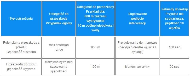
Z tabeli wynika, że czas jest krytycznym parametrem.
Należy także wziąć pod uwagę, że czas na podjęcie bezpiecznego manewru wynosi przynajmniej 3 x długość statku / prędkość.
Ostatni przypadek masowca “Shen Neng 1”, który osiadł na Australijskiej Wielkiej Rafie Koralowej w kwietniu 2010. Statek o długości 225 m płynący z prędkością 12 węzłów, na wykonanie bezpiecznego manewru potrzebował 110 sekund czasu. Dla porównania jednostka o długości 6 m potrzebuje na manewr tylko 4 sekund. Rozważmy bliżej przypadek statku pasażerskiego „Royal Majesty”, który osiadł na mieliźnie w 1995 roku w pobliżu wyspy Nantucket, Massachusetts.W tym przypadku statek znalazł się poza kursem z powodu problemów z GPS. Ścieżka ostatnich 5 mil morskich “Royal Majesty” pokazana jest na rysunku 10.
Gdyby rzeczywista pozycja statku była znana, wówczas nawigator patrząc na mapę zorientowałby się, że statek wejdzie na niebezpieczną mieliznę. Ale korzystając ze standardowych map z kolorowymi konturami nie jest całkowicie jasne, jak niebezpieczna jest sytuacja.
Aby wyjaśnić sprawę: dane batymetryczne NOAA wewnątrz rejonu XY oznaczonego na czerwono są zaprezentowane w zobrazowaniu trójwymiarowym w kolorach od czerwonego do niebieskiego na rysunku 11. Z tego rysunku widać jak dramatycznie podnosi się dno. Głębokość wody (ponad 14 m) pozostaje do ostatniego momentu i nagle staje się bardzo płytka na przestrzeni ostatnich 600m drogi statku.
Prędkość “Royal Majesty” wynosiła 14 węzłów, a więc przebycie drogi 600 m zajęło tylko 60 sekund. Można wyobrazić, że ten statek jest wyposażony w sonar z zakresem wykrywania 800 metrów, oraz z 60 stopniowym kątem widzenia w poziomie. Pole widzenia takiego sonaru jest naniesione na mapę batymetryczną NOAA na rysunku 12 w widoku z góry.
Widać wyraźnie, że statek Royal Majesty o całkowitej długości 173 m w pozycji jak na rysunku 12 miałby dostatecznie dużo czasu na wykonanie manewru uniknięcia kolizji z mielizną gdyby miał możliwość wykrycia sonarem FLS krawędzi mielizny.
Następny rysunek prezentuje przykład jak sonar FarSounder widziałby te podwodną scenę:
Na echogramie widoczna jest wyraźnie ostra krawędź mielizny. Alarm zostałby automatycznie uruchomiony. Więc sonar FLS jest cennym urządzeniem pozwalającym uniknąć kolizji lub wejścia na mieliznę.
Wnioski
Praktycznie podstawą do wypracowania decyzji o wyborze typu sonaru antykolizyjnego (FLS) jest znajomość potrzeby reakcji nawigatora na informacje i ostrzeżenia przekazywane przez sonar.
Wariant I
- Czy jest się właścicielem / armatorem dużego statku ?
- Czy woli się wykonywać manewr uniknięcia przeszkody bezpośrednio po jej wykryciu, zamiast zatrzymania się lub zwolnienia prędkości w celu zastanowienia się, która droga byłaby najlepsza, aby uniknąć kolizji ?
- Czy wymagane jest utrzymywanie stałej prędkości w celu oszczędzania czasu i paliwa ?
Jeśli odpowiedź brzmi “tak” na wszystkie trzy pytania, wówczas najlepszą opcją jest sonar o rzeczywistym zobrazowaniu 3D.
Wariant II
- Czy jest się właścicielem stosunkowo małej jednostki rekreacyjnej ?
- Czy można pozwolić sobie na zatrzymanie lub zmniejszenie prędkości w celu podjęcia decyzji o wyborze drogi do ominięcia wykrytej przeszkody ?
- Czy wydłużenie czasu podróży nie jest bardzo istotne?
Jeśli odpowiedź brzmi “tak”, to można dokonać wyboru tańszego sonaru skanującego o zobrazowaniu 2D.
W każdym wypadku sonary typu FLS czynią nawigację bezpieczniejszą.
Opracowanie firmy ESCORT SP. Z O.O. oparte o materiał firmy FarSounder, Inc.